The store will not work correctly when cookies are disabled.
  • My Account
  • Sign In
  • Compare Products
  • Create an Account
Company
  • About Us
  • Enertrols
  • Jobs & Career
  • Contact & Directions
  • Global locations

Contact

+1 248-476-0213

    ...

To product page!
  • Deutschland
  • Nederland
  • United Kingdom
  • 中国 (China)
  • 日本 (Japan)
  • Worldwide
ACE Controls Inc.
ACE Controls Inc.
  • Sign In
Toggle Nav
Menu
  • Products
    • Automation Control
      • Miniature Shock Absorbers
        • MC5 to MC75
          • MC5M
          • MC9M
          • MC10M
          • MC25M
          • MC30M
          • MC75M
          • MC25
          • MC75
        • MC150 to MC600
          • MC150M
          • MC225M
          • MC600M
          • MC150
          • MC225
          • MC600
        • MC150-V4A to MC600-V4A
          • MC150M-V4A
          • MC225M-V4A
          • MC600M-V4A
        • PMCN150 to PMCN600
          • PMCN150M
          • PMCN225M
          • PMCN600M
        • PMCN150-V4A to PMCN600-V4A
          • PMCN150M-V4A
          • PMCN225M-V4A
          • PMCN600M-V4A
        • SC190 to SC925
          • SC190M; 0 to 4
          • SC300M; 0 to 4
          • SC650M; 0 to 4
          • SC925M; 0 to 4
          • SC190; 0 to 4
          • SC300; 0 to 4
          • SC650; 0 to 4
          • SC925; 0 to 4
        • SC²25 to SC²190
          • SC25M; 5 to 7
          • SC75M; 5 to 7
          • SC190M; 5 to 7
        • SC²300 to SC²650
          • SC300M; 5 to 9
          • SC650M; 5 to 9
          • SC300; 5 to 9
          • SC650; 5 to 9
        • SC25-HC to SC650-HC
          • SC25M-HC
          • SC75M-HC
          • SC190M-HC
          • SC300M-HC
          • SC650M-HC
          • SC300-HC
          • SC650-HC
        • Show all
      • Industrial Shock Absorbers
        • MC33 to MC64
          • MC33M
          • MC36M
          • MC45M
          • MC64M
          • MC33
          • MC36
          • MC45
          • MC64
        • MC33-V4A to MC64-V4A
          • MC33M-V4A
          • MC45M-V4A
          • MC64M-V4A
        • MC33-HT to MC64-HT
          • MC33M-HT
          • MC45M-HT
          • MC64M-HT
          • MC33-HT
          • MC45-HT
          • MC64-HT
        • MC33-LT to MC64-LT
          • MC33M-LT
          • MC45M-LT
          • MC64M-LT
          • MC33-LT
          • MC45-LT
          • MC64-LT
        • SC33 to SC45
          • SC33
          • SC45
        • MA/ML33 to MA/ML64
          • MA/ML33M
          • MA/ML36M
          • MA/ML45M
          • MA/ML64M
          • MA/ML33
          • MA/ML36
          • MA/ML45
          • MA/ML64
        • SALD1/2 to SALD1 1/8
          • SALD1/2-P Primary
          • SALD3/4-P Primary
          • SALD1 1/8-P Primary
        • SALDN3/4
          • SALDN3/4-RF Front Flange
          • SALDN3/4-RR Rear Flange
      • Heavy Industrial Shock Absorbers
        • CA2 to CA4
          • CA2
          • CA3
          • CA4
        • A1 1/2 to A3
          • A1 1/2
          • A2
          • A3
      • Profile Dampers
        • TUBUS TA
          • TA
        • TUBUS TS
          • TS
        • TUBUS TR
          • TR
        • TUBUS TR-H
          • TR-H
        • TUBUS TR-L
          • TR-L
        • TUBUS TR-HD
          • TR-HD
      • Damping Pads
        • SLAB 030 to SLAB 300
          • SL-030-12
          • SL-030-25
          • SL-100-12
          • SL-100-25
          • SL-300-12
          • SL-300-25
      • Accessories
    • Motion Control
      • Industrial Gas Springs – Push Type
        • GS-8 to GS-70
          • GS-8
          • GS-10
          • GS-12
          • GS-15
          • GS-19
          • GS-22
          • GS-28
          • GS-40
          • GS-70
        • GS-8-V4A to GS-40-VA
          • GS-8-V4A
          • GS-10-V4A
          • GS-12-V4A
          • GS-15-V4A
          • GS-19-V4A
          • GS-22-V4A
          • GS-28-V4A
          • GS-40-V4A
          • GS-15-VA
          • Show all
        • GST-40 Tandem
          • GST-40
      • Industrial Gas Springs – Pull Type
        • GZ-15 to GZ-40
          • GZ-15
          • GZ-19
          • GZ-28
          • GZ-40
        • GZ-15-V4A to GZ-40-VA
          • GZ-15-V4A
          • GZ-19-V4A
          • GZ-28-V4A
          • GZ-40-V4A
          • GZ-19-VA
          • GZ-28-VA
          • GZ-40-VA
      • Hydraulic Dampers
        • DVC-32 and DVC-2 to DVC-6
          • DVC-32
          • DVC-2 to DVC-6
        • HBD-15 to HBD-40
          • HBD-15
          • HBD-22
          • HBD-28
          • HBD-40
        • HB-12 to HB-70
          • HB-12
          • HB15
          • HB22
          • HB28
          • HB40
          • HB50
          • HB-70
        • SOL-28 - Solar Dampers
          • SOL-28-5078/20682
          • SOL-28-20684
          • SOL-28-5095
          • SOL-28-21215/20714
          • SOL-28-21305
          • SOL-28-20816 VA
          • SOL-28-20674
          • SOL-28-690030
        • MOD 28
          • MD-28
      • Hydraulic Feed Controls
        • VC25
          • VC25FT
          • VC25F
        • MA, MVC
          • MA30M
          • MA50M
          • MA35M
          • MA150M
          • MVC225M
          • MVC600M
          • MVC900M
          • MA35
          • MA150
          • Show all
      • Rotary Dampers
        • FRT-E2
          • FRT-E2
          • FRT-E2-G1
        • FRT-G2
          • FRT-G2
          • FRT-G2-G1
        • FRT-C2 and FRN-C2
          • FRT-C2
          • FRT-C2-G1
          • FRN-C2-R
          • FRN-C2-R-G1
          • FRN-C2-L
          • FRN-C2-L-G1
        • FRT-D3 and FRN-D3
          • FRT-D3
          • FRT-D3-G1
          • FRN-D3-R
          • FRN-D3-R-G1
          • FRN-D3-L
          • FRN-D3-L-G1
        • FRT-F2/K2 and FRN-F2/K2
          • FRT-F2/K2
          • FRN-F2/K2-R
          • FRN-F2/K2-L
        • FFD
          • FFD-SS-R
          • FFD-SS-L
          • FFD-FS-R
          • FFD-FS-L
          • FFD-SW-R
          • FFD-SW-L
          • FFD-FW-R
          • FFD-FW-L
        • FDT
          • FDT
        • FDN
          • FDN-R
          • FDN-L
        • FYN-P1
          • FYN-P1-R
          • FYN-P1-L
        • Show all
      • Accessories
    • Vibration Control
      • Vibration-Isolating Pads
        • SLAB 170 to SLAB 275
          • SL-170-12
          • SL-170-25
          • SL-210-12
          • SL-210-25
          • SL-275-12
          • SL-275-25
        • CEL
          • CEL-200
          • CEL-300
        • PAD
          • PAD
      • Low Freq. Pneumatic Levelling Mounts
        • PLM
          • PLM
        • PAL-3 to PAL-9
          • PAL-3
          • PAL-5.5
          • PAL-9
        • PAL-18 to PAL-1000
          • PAL-18
          • PAL-21
          • PAL-36
          • PAL-55
          • PAL-75
          • PAL-133
          • PAL-255
          • PAL-416
          • PAL-1000
      • Accessories
    • Safety Products
      • Safety Shock Absorbers
        • SCS33 to SCS64
          • SCS33
          • SCS45
          • SCS64
        • SCS38 to SCS63
          • SCS38
          • SCS50
          • SCS63
        • CB63 to CB160
          • CB63
          • CB100
          • CB160
        • EB63 to EB160
          • EB63
          • EB100
          • EB160
      • Safety Bumpers
        • TUBUS TC and TC-S
          • TC
          • TC-S
        • TUBUS TI
          • TI 1-Bellow
          • TI 2-Bellows
          • TI 3-Bellows
        • Crash Dampers
          • CD 20
          • CD 21
          • CD 38
          • CD 63
          • CD 88
      • Clamping Elements
        • LOCKED PL
          • PL
        • LOCKED PLK
          • PLK
        • LOCKED SL
          • SL
        • LOCKED SLK
          • SLK
        • LOCKED LZ-P
          • LZ-P
        • LOCKED PN
          • PN
        • LOCKED PRK
          • PRK
        • LOCKED R
          • R
          • R-Z
      • Viscoelastic Shock Absorbers
        • VS
          • VS-BA1-FC Front Flange
          • VS-BA1-FA Rear Flange
          • VS-BA5-FC Front Flange
          • VS-BA5-FA Rear Flange
          • VS-BXLR-FC Front Flange
          • VS-BXLR-FA Rear Flange
          • VS-BALR-FC Front Flange
      • Accessories
  • Applications
    • Automation Control
    • Motion Control
    • Vibration Control
    • Safety Products
  • Calculations
  • Service & Downloads
    • CAD-Drawings
    • Catalogs and more
    • Mounting Instructions
    • Mobile Apps
    • Knowledge
      • Industrial Shock Absorbers
      • Calculation Bases for the Design of Industrial Shock Absorbers
      • Profile Dampers
      • Pallet Stoppers
    • ACE Academy
    • Certifications
  • News & Press
    • Press Releases
    • Trade Shows
  • Sales
    • Where to Buy
    • Quick Order - eShop
    • Price Request
    • Procurement
    • Service, Support & Info
  • Blog
Account
My Cart

Calculation Bases

Design of Industrial Shock Absorbers

ACE shock absorbers provide linear deceleration and are therefore superior to other kinds of damping element. With the help of the overview of the calculation bases for the design of a shock absorber you will be able to select the right industrial shock absorber for your project from the ACE web catalogue.

Key to symbols used

Applications

Effective Weight (me)

It is easy to calculate around 90 % of applications knowing only the following five parameters:

  1. Abzubremsende Masse (Gewicht)                     m    [kg]
  2. Aufprall- oder Auffahrgeschwindigkeit             vD   [m/s]
  3. Evtl. vorhandene zusätzliche Antriebskraft      F     [N]
  4. Anzahl der Hübe oder Takte pro Stunde           x      [1/h]
  5. Anzahl Stoßdämpfer parallel                              n

Calculate the correct shock absorber according to your application

Key to symbols used

Symbol Unit Description Symbol Unit Description
W1  Nm Kinetic energy per cycle 3ST 1 to 3 tall torque factor (normally 2.5)
W2  Nm Propelling force energy per cycle M Nm Propelling torque
W3 Nm Total energy per cycle (W1 + W2) I kgm2 Moment of Inertia
1W4 Nm/hr Total energy per hour (W3 · c) g m/s2 Acceleration due to gravity = 9.81
me kg Effective weight h m Drop height excl. shock absorber stroke
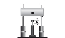
m kg Mass to be decelerated s m Shock absorber stroke
n   Number of shock absorbers (in parallel) L/R/r m Radius
2v m/s Velocity at impact Q N Reaction force
2vD m/s Impact velocity at shock absorber μ   Coefficient of friction
ω rad/s Angular velocity at impact t s Deceleration time
F N Propelling force a m/s2 Deceleration
c 1/hr Cycles per hour α ° Side load angle
P kW Motor power β ° Angle of incline
1 All mentioned values of W4 in the capacity charts are only valid for room temperature. There are reduced values at higher temperature ranges.
2 v or vD is the final impact velocity of the mass. With accelerating motion the final impact velocity can be 1.5 to 2 times higher than the average. Please take this into account when calculating kinetic energy.
3 ST =^ relation between starting torque and running torque of the motor (depending on the design)
In all the following examples the choice of shock absorbers made from the capacity chart is based upon the values of (W3), (W4), (me) and the desired shock absorber stroke (s).
 

Note:
When using several shock absorbers in parallel, the values (W3), (W4) and (me) are divided according to the number of units used.

Reaction force Q [N]
Für alle Beispiele gilt:

Q = (1,5 · W3) / s

Stopping time t [s]
Für alle Beispiele gilt:

t = (2,6 · s) / vD

Deceleration a [m/s2]
Für alle Beispiele gilt:

a = (0,75 · vD2) / s

Approximate values assuming correct adjustment. Add safety margin if necessary. (Exact values will depend upon actual application data and can be provided on request.)

Applications


Application Formulae Example

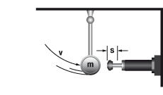
1. Mass without propelling force

W1 = m · v2 · 0,5
W2 = 0
W3 = W1 + W2
W4 = W3 · x
vD = v
me = m

m = 100 kg
v = 1,5 m/s
x = 500 1/h
s = 0,050 m (gewählt)

W1 = 100 · 1,52 · 0,5 = 113 Nm
W2 = 0
W3 = 113 + 0 = 113 Nm
W4 = 113 · 500 = 56500 Nm/h
me = m = 100 kg

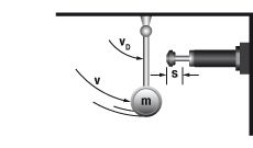
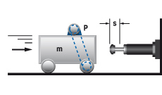
2. Mass with propelling force

W1 = m · v2 · 0,5
W2 = F · s
W3 = W1 + W2
W4 = W3 · x
vD = v
me = (2 · W3) / vD2
 
2.1 bei senkrechter Bewegung nach oben
W2 = (F – m · g) · s
 
2.2 bei senkrechter Bewegung nach unten
W2 = (F + m · g) · s
m = 36 kg
1v = 1,5 m/s
F = 400 N
x = 1000 1/h
s = 0,025 m (gewählt)


W1 = 36 · 1,52 · 0,5 = 41 Nm
W2 = 400 · 0,025 = 10 Nm
W3 = 41 + 10 = 51 Nm
W4 = 51 · 1000 = 51000 Nm/h
me = 2 · 51 : 1,52 = 45 kg


1 v is the fi nal impact velocity of the mass:
With pneumaticallypropelled systems this can be 1.5 to 2 times the average velocity. 
Please take this into account when calculating energy.

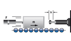
3. Mass with motor drive

W1 = m · v2 · 0,5
W2 = (1000 · P ·HM · s) / v
W3 = W1 + W2
W4 = W3 · x
vD = v
me = (2 · W3) / vD2

m = 800 kg
v = 1,2 m/s
HM = 2,5
P = 4 kW
x = 100 1/h
s = 0,100 m (gewählt)

W1 = 800 · 1,22 · 0,5 = 576 Nm
W2 = 1000 · 4 · 2,5 · 0,1 : 1,2 = 834 Nm
W3 = 576 + 834 = 1410 Nm
W4 = 1410 · 100 = 141000 Nm/h
me = 2 · 1410 : 1,22 = 1958 kg

Note: Do not forget to include the rotational energy of
motor, coupling and gearbox into calculation for W1

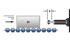
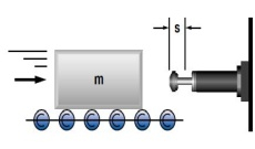
4. Mass on driven rollers

W1 = m · v2 · 0,5
W2 = m · μ · g · s
W3 = W1 + W2
W4 = W3 · x
vD = v
me = (2 · W3) / vD2

m = 250 kg
v = 1,5 m/s
x = 180 1/h
(Stahl/Guss) μ = 0,2 
s = 0,050 m (gewählt)

W1 = 250 · 1,52 · 0,5 = 281 Nm
W2 = 250 · 0,2 · 9,81 · 0,05 = 25 Nm
W3 = 281 + 25 = 306 Nm
W4 = 306 · 180 = 55080 Nm/h
me = 2 · 306 : 1,52 = 272 kg

5. Swinging mass with propelling force

W1 = m · v2 · 0,5 = 0,5 · J · ω2
W2 = (M · s) / R
W3 = W1 + W2
W4 = W3 · x
vD = (v · R) / L = ω · R
me = (2 · W3) / vD2

m = 20 kg
v = 1 m/s
M = 50
R = 0,5 m
L = 0,8 m
x = 1500 1/h
s = 0,012 m (gewählt)

W1 = 20 · 12 · 0,5 = 10 Nm
W2 = 50 · 0,012 : 0,5 = 1,2 Nm
W3 = 10 + 1,2 = 11,2 Nm
W4 = 306 · 180 = 16800 Nm/h
vD  = 1 · 0,5 : 0,8 = 0,63 m/s 

me = 2 · 11,2 : 0,632 = 56 kg

6. Free falling mass

W1 = m · g · h
W2 = m · g · s
W3 = W1 + W2
W4 = W3 · x
vD = √2 · g · h
me = (2 · W3) / vD2

m = 30 kg
h = 0,5 m
x = 400 1/h
s = 0,050 m (gewählt)

W1 = 30 · 0,5 · 9,81 = 147 Nm
W2 = 30 · 9,81 · 0,05 = 15 Nm
W3 = 147 + 15 = 162 Nm
W4 = 162 · 400 = 64800 Nm/h
vD  = √2 · 9,81 · 0,5 = 3,13 m/s 

me = 2 · 162 : 3,132 = 33 kg

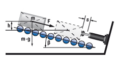
6.1 Mass rolling/sliding down incline

W1 = m · g · h = m · vD2 · 0,5
W2 = m · g · sinβ · s
W3 = W1 + W2
W4 = W3 · x
vD = √2 · g · h
me = (2 · W3) / vD2

6.1a bei senkrechter Bewegung nach oben
W2 = (F – m · g· sinβ) · s
 
6.1b bei senkrechter Bewegung nach unten
W2 = (F + m · g· sinβ) · s

m = 500 kg
h = 0,1 m
x = 200 1/h
ß = 10 °C

W1 = 500 · 9,81 · 0,1 = 490,5 Nm
W2 = 50 · 9,81 · sin(10) · 0,075 = 63,9 Nm
W3 = 490,5 + 63,9 = 554,4 Nm
W4 = 554,4 · 200 = 11880,0 Nm/h

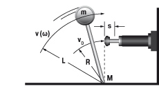
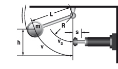
6.2 Mass free falling about a pivot point

W1 = m · g · h
W2 = 0
W3 = W1 + W2
W4 = W3 · x
vD = √2 · g · h · (R / L)
me = (2 · W3) / vD2

tan α = s / R

m = 50 kg
h = 1 m
x = 50 1/h
R = 300 mm
L = 500 mm

W1 = 50 · 9,81 · 1 = 490,5 Nm
W2 = 0
W3 = 490,5 + 0 = 490,5 Nm
W4 = 490,5 · 50 = 24525,0 Nm/h

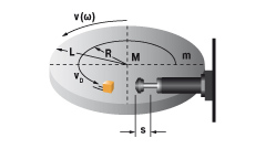
7. Rotary index table with propelling torque

W1 = m · v2 · 0,25 = 0,5 · J · ω2
W2 = (M · s) / R
W3 = W1 + W2
W4 = W3 · x
vD = (v · R) / L = ω · R
me = (2 · W3) / vD2

m = 1000 kg
v = 1,1 m/s
M = 1000 Nm
s = 0,050 m (gewählt)
L = 1,25 m
R = 0,8 m
x = 100 1/h

W1 = 1000 · 1,12 · 0,25 = 303 Nm
W2 = 300 · 0,025 : 0,8 = 63 Nm
W3 = 28 + 9 = 366 Nm
W4 = 37 · 1200 = 36600 Nm/h
vD = 1,1 · 0,8 : 1,25 = 0,7 m/s
me = · 366 : 0,72 = 1494 kg

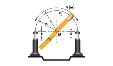
8. Swinging arm with propelling torque (uniform weight distribution)

W1 = m · v2 · 0,17 = 0,5 · J · ω2
W2 = (M · s) / R
W3 = W1 + W2
W4 = W3 · x
vD = (v · R) / L = ω · R
me = (2 · W3) / vD2

J = 56 kgm2
ω = 1 1/s
M = 300 Nm
s = 0,025 m (gewählt)
L = 1,5 m
R = 0,8 m
x = 1200 1/h

W1 = 0,5 · 56 · 12 = 28 Nm
W2 = 300 · 0,025 : 0,8 = 9 Nm
W3 = 28 + 9 = 37 Nm
W4 = 37 · 1200 = 44400 Nm/h
vD = 1 · 0,8 = 0,8 m/s
me = 2 · 37 : 0,82 = 116 kg

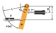
9. Swinging arm with propelling force (uniform weight distribution)

W1 = m · v2 · 0,17 = 0,5 · J · ω2
W2 = (F · r · s) / R = (M · s) / R
W3 = W1 + W2
W4 = W3 · x
vD = (v · R) / L = ω · R
me = (2 · W3) / vD2

m = 1000 kg
v = 2 m/s
F = 7000 N
M = 4200 Nm
s = 0,050 m (gewählt)
r = 0,6 m
R = 0,8 m
L = 1,2 m
x = 900 1/h

W1 = 1000 · 22 · 0,17 = 680 Nm
W2 = 7000 · 0,6 · 0,05 : 0,8 = 263 Nm
W3 = 680 + 263 = 943 Nm
W4 = 943 · 900 = 848700 Nm/h
vD = 2 · 0,8 : 1,2 = 1,33 m/s
me = 2 · 943 : 1,332 = 1066 kg

10. Mass lowered at controlled speed

W1 =m · v2 · 0,5
W2 = m · g · s
W3 = W1 + W2
W4 = W3 · x
vD = v
me = (2 · W3) / vD2

m = 6000 kg
v = 1,5 m/s
s = 0,305 m (gewählt)
x = 60 1/h

W1 = 6000 · 1,52 · 0,5 = 6750 Nm
W2 = 6000 · 9,81 · 0,305 = 17952 Nm
W3 = 6750 + 17 952 = 24702 Nm
W4 = 24702 · 60 = 1482120 Nm/h
me = 2 · 24702 : 1,52 = 21957 kg

 
Use calculation tool and order online

Effective Weight (me)

The effective weight (me) can either be the same as the actual weight (examples Aand C), or it can be an imaginary weight representing a combination of the propelling force or lever action plus the actual weight (examples B and D).

Einsatzfall Beispiel

A    Mass without propelling force

m = 100 kg
vD = v = 2 m/s
W1 = W3 = 200 Nm
me = (2 · 200) / 4 = 100 kg

FORMULA: ME = M

B    Mass with propelling force

m = 100 kg
F = 2000 N
vD = v = 2 m/s
s = 0,1 m
W1 = 200 Nm
W2 = 200 Nm
W3 = 400 Nm
me = (2 · 400) / 4 = 200 kg

FORMEL: ME = (2 · W3) / VD2

C    Mass without propelling force direct against shock absorber

m = 20 kg
vD = v = 2 m/s
W1 = W3 = 40 Nm
me = (2 · 40) / 22 = 20 kg

FORMEL: ME = M

D    Mass without propelling force with mechanical advantage

m = 20 kg
v = 2 m/s
vD = 0,5 m/s
s = 0,1 m
W1 = W3 = 40 Nm
me = (2 · 40) / 0,52 = 320 kg

FORMEL: ME = (2 · W3) / VD2


Knowledge

  • Industrial Shock Absorbers
  • Calculation Bases for the Design of Industrial Shock Absorbers
  • Profile Dampers
  • Pallet Stoppers

  • Products
  • Automation Control
  • Motion Control
  • Vibration Control
  • Safety Products
  • Applications
  • Automation Control
  • Motion Control
  • Vibration Control
  • Safety Products
  • Calculations
  • Automation Control
  • Motion Control
  • Vibration Control
  • Safety Products
  • Service & Downloads
  • CAD-Drawings
  • Catalogs and more
  • Mounting Instructions
  • Mobile Apps
  • Knowledge
  • ACE Academy
  • Certifications
  • News & Press
  • Press Releases
  • Trade Shows
  • Sales
  • Where to Buy
  • Quick Order - eShop
  • Price Request
  • Procurement
  • Service, Support & Info
  • Blog

ACE Controls Inc.

23435 Industrial Park Drive
US - 48335 Farmington Hills, Michigan

  • Company
  • Enertrols
  • Jobs & Career
  • Contact & Directions

ACE Stoßdämpfer GmbH © 2023

  • Cookie Settings
  • Terms and Conditions
  • Privacy Policy
  • Imprint
ACE is not responsible for content on external linked websites.
Successfully logged in